Everybody wants to give FPGA development a try and here’s a great way to get into it. You can build your own Persistence of Vision display using a $30 dev board. It’s a fun project, and you’ll learn quite a bit about designing for an FPGA, as well as using the Quartus design software.
The inspiration for this article comes from [vpecanins] who did an example project where you wave the board back and forth and a message appears in mid air. This uses the MAX1000, a pretty powerful yet odd FPGA board for about $30. It contains an Intel MAX10 (when did Intel start making FPGAs? Remember, Intel bought Alterra back in 2015). I find the board odd because it also holds an accelerometer that you can talk to using SPI. That’s a little strange for a generic FPGA board, but paired with eight on-board LEDs it’s perfect for this demo.
Since I didn’t find any written documentation for this example, I thought we’d help out and take you on a step-by-step tour of the project. What’s more, in a future installment, I’ll show you how to make some significant changes to the tutorial that will make it even more practical as a base for other projects.
Just for motivation, have a look at the video below to see what the project does. I modified the text (WD5GNR is my call sign), of course. The effect is better in real life, but the video will give you the idea. The FPGA monitors the accelerometer reverses the order for flashing the LEDs on and off to form the characters. It is a pretty impressive demo since it takes advantage of the unique features of the board, is non-trivial, and isn’t too much Verilog to swallow if you are just getting started.
Prerequisites
To start with, you’ll need to install Quartus. The Lite edition is free and very capable. You can download the files and open the test0.qpf file in the demo02_led_text directory. You may get a nasty dialog about replacing the database if you have a newer version of Quartus than the original files used. You can safely agree to that.
File Tour
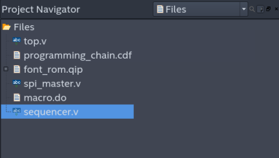
On the project navigator inside Quartus, you can select Files and you’ll see the project has only a few:
- top.v – The main Verilog code.
- programming_chain.cdf – This file should tell Quartus how to program the configuration into the chip, but it is missing. That’s not a problem though. It isn’t really necessary and it is easy to recreate.
- font_rom.qip – A component that uses Altera IP (Intellectual Property) to create a ROM with the character patterns in it.
- spi_master.v – Code for talking to the accelerometer.
- macro.do – This file doesn’t actually exist and is apparently left over from the author’s earlier efforts.
- sequencer.v – Code for using the accelerometer.
 If you expand …read more
Source:: Hackaday