We’ve read a lot about oscillators, but crystal oscillators seem to be a bit of a mystery. Hobby-level books tend to say, build a circuit like this and then mess with it until it oscillates. Engineering texts tend to go on about loop gains but aren’t very clear about practice. A [circuit digest] post that continues a series on oscillators has a good, practical treatment of the subject.
Crystals are made to have a natural resonant frequency and will oscillate at that frequency or a multiple thereof with the proper excitation. The trick, of course, is finding the proper excitation.
The post starts with a basic model of a crystal having a series capacitance and inductance along with a resistance. There’s also a shunt or parallel capacitor. When you order a crystal, you specify if you want the resonant frequency in series or parallel mode — that is, which of the capacitors in the model you want to resonate with the inductor — so the model has actual practical application.
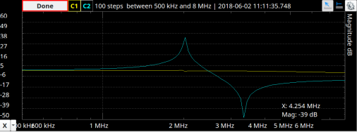
By applying the usual formula for resonance on the model you’ll see there is a null and a peak which corresponds to the two resonance points. The dip is the series frequency and the peak is the parallel. You can actually see a trace for a real crystal in a recent post we did on the Analog Discovery 2. It matches the math pretty well, as you can see on the right.
You might wonder if you could forego a crystal and just use the components in the model. In theory, yes. But the Q — the ratio of reactance to resistance — will be much lower than a crystal. A crystal is also more stable than typical resistors, capacitors, and inductors, which is why they find use where you need an actual accurate frequency. The high Q makes crystals useful in narrow-band filters, as well.
There are several common oscillators architectures, and a typical design procedure is to start with one and compute the values required. The post looks at a Colpitts oscillator. You can usually tell a Colpitts oscillator by remembering it starts with C and the feedback loop has a split capacitor (as opposed to a tapped inductor). The post also looks at Pierce oscillator and several digital oscillators. However, the post stops short of actually going through the design computations. However, it is still a lot of good information. If you can bias an inverting amplifier, you should be good to go.
You can test a crystal by injecting a resonant frequency into it. We’ve also seen SDRs pressed into service for testing.
Source:: Hackaday