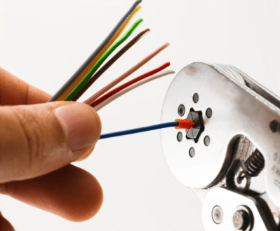
We think it’s pretty safe to assume that most of the electrical connections our readers are making out there involve solder or solder paste. But we’ve all made a crimp connection or two in our lifetimes. Maybe you’ve squeezed a butt connector here and there, or made an Ethernet cable. Beyond getting the wiring order right in the Ethernet cable, how much did you wonder about what was happening inside the connector?
It may seem like solder is the superior option for making a low-resistance electrical connection. After all, you’re welding metals together with another metal. And this is usually all fine and good for circuit boards with sedentary indoor lives. But if a joint needs to be mechanically stable and survive in potentially harsh environments, you don’t want an alloy holding things together. You want metal to metal contact, and crimping is where it’s at.
A well-made crimp should last for several decades, but as Shelley Green explained in her talk at the 2019 Hackaday Superconference, good quality crimps don’t happen by accident. Good crimps are meticulously designed, and carefully executed from start to finish.
Crimping Dynamics
Shelley compares failed crimps to the O-ring disaster that plagued the Space Shuttle Challenger. Things like O-rings and crimp connections may seem small and inconsequential, but a failure to pay attention to their physical properties can mean catastrophe.
So what goes into making a good crimp? It’s all a matter of physics. The point of crimping is to make a connection with the lowest possible resistance. A permanent mechanical crimp involves forcing conductors together so that electricity can flow from A to B. Macro-structurally, good crimps occur when the connector is deformed past the yield point of the metal, and there is uniform deformation of the wires.
As Shelley explains, this bulk deformation is not the reason for low resistance, but the residual stresses between the conductors and the connector are responsible for keeping the system together.
If you look at the micro-structure of a crimp connection under a scanning electron microscope, the surfaces are quite rough, and there are only a few spots that actually make contact with each other. The high-profile places where contact actually occurs — called asperity spots or a-spots in materials science — are the real indicators of resistance rating.
The design of a good crimp has many aspects. First, you have to think about the application, the environment the crimp will live in, and the desired outcome of the crimp. Then come the implementation details — the crimp style, the wire, the terminals, and everyone’s favorite, the tooling. The fatter the cable gets, the more important all of these things become.
Shelley also discusses the merits of various crimp styles for different applications and environments, citing that the shape of the indenter can mean big differences in durability.
The Truth is in the Testing
In closing, Shelley touches on the testing schemes commonly used for crimped connections. …read more
Source:: Hackaday