In the first installment of this series we had a brief look at the steps needed to get a bare-metal application running on an STM32 microcontroller. While this allowed us to quickly get to the juicy stuff, there are two essential elements which make an MCU so easy to use. One is found on the hardware side, in the form of so-called memory-mapped I/O (input/output), the other is the information contained in the files that are passed to the linker when we build a firmware image.
Memory-mapping of hardware peripheral registers is a straightforward way to make them accessible to the processor core, as each register is accessible as a memory address. This is both convenient when writing the firmware code, as well as for testing, as we can use a memory mapping specific for unit or integration testing.
We will take an in-depth look at this way of testing, as well as how these linker script files are connected to the memory layout.
It’s Memory All the Way Down
Akin to UNIX’s ‘everything is a file’ philosophy, for Cortex-M MCUs it is fair to say that ‘everything is a memory address’. Mapping devices onto a flat memory space is actually a common approach for computer systems. Even Intel x86 systems used this approach, with ISA, PCI, SMBus, AGP and PCIe devices detected at boot time and mapped into the flat addressing space.
As an aside, this property also led to the odd situation on 32-bit x86 systems where the ~4 GB memory address space limit could not support 4 GB RAM, because the video card’s RAM would also be mapped into the addressing space. This got problematic as the VRAM on GPUs increased beyond 512 MB, and all of this had to be mapped into the same addressing space.
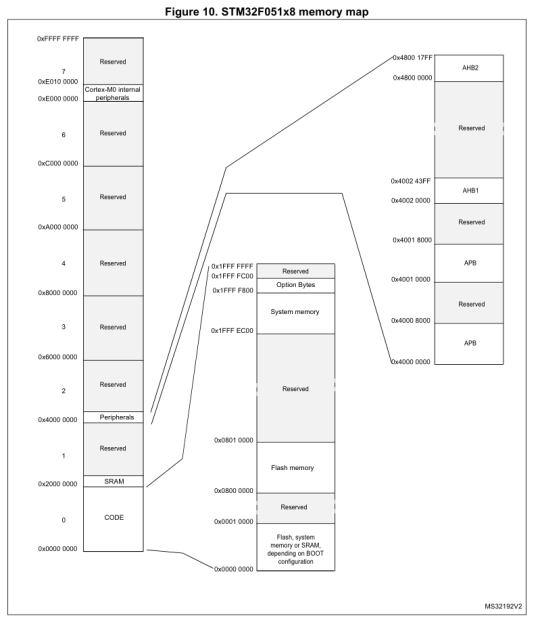
But back to microcontrollers. Cortex-M MCUs also have a 32-bit address space, from 0x0000 0000 to 0xFFFF FFFF:
By default, the Flash memory on STM32F0 MCUs starts at 0x0800 0000, and the starting with 0x0000 0000 is used to map to the boot medium. This is Flash by default, but can be switched to map to external or internal RAM as well using the BOOT0/1 configuration bits:
This shows how flexible memory mapping is: without having to change the first-stage bootloader, the same address can always be loaded on boot, with the boot area’s contents easily switched to a different source.
It’s linking time
Before the compiled code can be assembled into the final firmware image, the linker tool has to know how to lay out the data as well as a few other details, such as the entry point. This information is described in a linker script, which uses a syntax the linker tool (usually ld) understands. Let’s run through the linker script for the STM32F042 target as an example:
ENTRY (Reset_Handler)
This specifies the symbol of the section (function) that will be put in the resulting binary file as the …read more
Source:: Hackaday