If you follow audiophile reviewers, you’ll know that their stock-in trade is a very fancy way of saying absolutely nothing of quantifiable substance about the subject while sounding knowledgeable about imagined differences between devices that are all of superlative quality anyway. If you follow us, we’ll tell you that the only reviews that matter are real-world measurements of audio performance, and blind listening tests. We don’t have to tell you how to listen to music, but perhaps it’s time in our Know Audio series to look at how audio performance is measured.
Before reaching for the bench, it’s first necessary to ask just what we are measuring. What are the properties which matter in an audio chain, or in other words, just what is it that makes an audio device good?
Why Does A Rock Guitar Sound Angry While A Classical Guitar Doesn’t?
There are of course many things than can be measured, but the one which matters the most in this context is probably distortion. You’re probably used to distortion in music, while a classical guitar sounds like a string being plucked, a rock guitar sounds… angry.
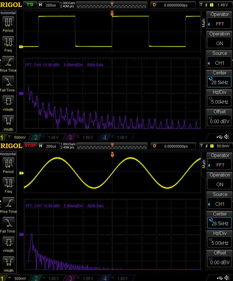
This is because the rock guitarist uses an effects pedal which induces audible distortion onto the otherwise pretty clean guitar sound. There are many different guitar effects pedals to be found, but some of the simplest merely drive an amplifier into clipping to make something closer to a square wave. But to understand what’s really going on, it’s necessary to look at the waveform not in the time domain as a sine wave or a square wave, but in the frequency domain as a spectrum.
If you were to take a perfect sine wave oscillator and plug it into a spectrum analyser, you would expect to see a single peak corresponding to the frequency of the sine wave. If you apply distortion to that sine wave, the spectrum analyser would start to show peaks at other frequencies depending on what type of distortion is being applied.
It’s a subject we’ve looked at in detail here at Hackaday in the past, and we’re guessing that many of you will be familiar with the mathematical derivation of a square wave from a series of harmonic sine waves. Distortion in an audio device is measured by looking at these extra peaks in the spectrum, and is expressed as either a dB value or a percentage indicating their relative strength compared to that of the original signal. For those guitar pedals the figure will be in the tens of percent, while for a good quality audio amplifier it will be only a fraction of a percent. It’s also usual to see the figure quoted as THD+N which indicates the noise component in the rest of the spectrum, as well as seeing it quoted for a single (usually 1kHz) frequency.
Measuring distortion is a superficially simple process, but in practice constructing an instrument to do so effectively is not an easy task. A device under test is fed with as pure a sine wave as can be generated, and the RMS voltage of its output is measured both directly from it and through a notch filter which removes the fundamental frequency of the sine wave. The idea is that the filtered signal returns only the component of the output which is due to the distortion, and thus can be compared to the full figure to derive that relative figure.
The designer of the instrument thus has several significant hurdles to overcome, because not only must their oscillator and filter be as near perfect as can be attained, but the rest of their analogue signal chain must not contribute to the distortion being measured. This is made even more difficult by a typical instrument requiring these characteristics across a wide frequency range; if a single frequency filter is a challenge then a variable one is much more so. A modern audio analyser will typically be a computer-controlled combination of digital and analogue instrumentation with the oscillator and measurements replaced by a very high quality DAC and ADC, while the filter retains an analogue circuit.
From A Light Bulb To The Digital Domain
The first HP product was the HP200A, a high quality audio oscillator that famously had an incandescent bulb as a non-linear element in its circuitry as a means to stabilise the amplitude and thus reduce the distortion of its output. This idea forms the basis of subsequent steps to reduce oscillator distortion, with improved feedback and AGC circuits.
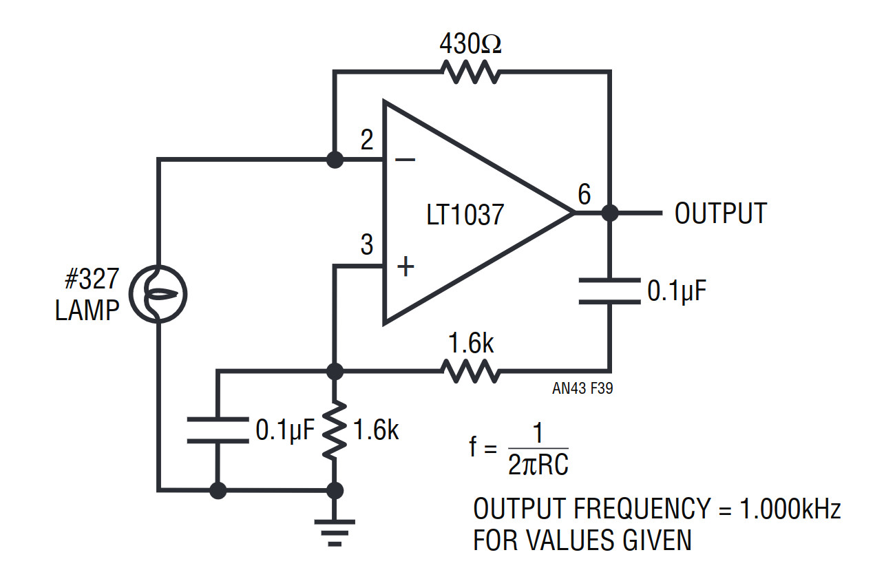
It’s suggested that you read Linear Technologies app note 43, in which Jim Williams delivers a comprehensive introduction to this topic, and then Cheng-We Pei’s note on a low distortion oscillator using an RMS-to-DC converter in its feedback loop.
Unfortunately, most inexpensive benchtop function generators don’t provide this low level of distortion, either relying on a low-pass filter to distort a square wave into something approximating a sine wave, or using a simple DAC for digital synthesis, so for audio measurement it’s worth looking for an unloved older analogue oscillator.
HP continued making derivatives of the 200A for many decades and innumerable companies produced clones and copies, so it’s comparatively easy to find older oscillators on the second-hand or surplus market.
The rest of the components are somewhat more difficult to find, because those filters are expensive to produce and thus an audio analyser can be an eye-wateringly expensive device. Even older instruments hold their value, and I consider myself exceptionally lucky to have secured my all-analogue 1970s-era HP334A distortion analyser without parting with the GDP of a small country. Given a suitably high quality ADC it’s possible to take the approach of filtering in the digital domain, however this may be beyond the capabilities of a mundane sound card. I investigated this idea a few years ago in an April Fool post about gold cables, and though the cable was a joke it’s still a valid measurement technique to which I might return in due course.
So this should have served as a basic primer in audio distortion and why it’s important to consider for your listening pleasure. There will be a further Know Audio piece on distortion to follow, in which we take a look at real-world distortion measurements and take a closer look at the instruments.